Since I
build displacement hulls, I didn't need to buy expensive props that would be hidden most
of the time in a kort nozzle. I decided to make my own and can make five props from a
sheet of brass that costs around $2.00.
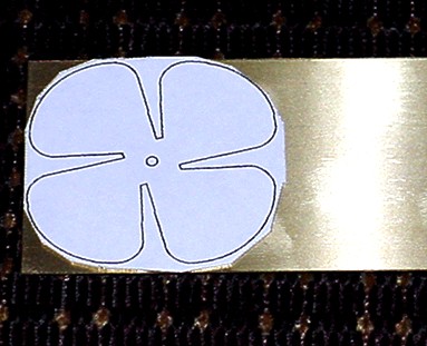
If
you have a graphics program you can use this pattern to make your own props.
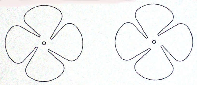
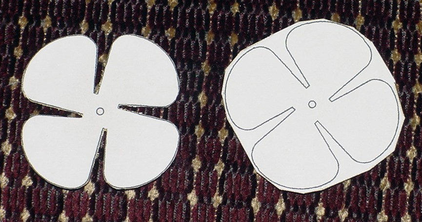
First I
drew a pattern for a left and right
handed prop, then I scale it to the
size I needed and print it out.
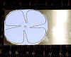 After I printed the pattern, I used spray adhesive to stick
it to a sheet of brass stock.
After I printed the pattern, I used spray adhesive to stick
it to a sheet of brass stock.
 I trimmed the stock with tin snips as close as possible. Then I
used a Dremel Moto-tool with a fiberglass cut off wheel to trim to the outline of the
prop.
I trimmed the stock with tin snips as close as possible. Then I
used a Dremel Moto-tool with a fiberglass cut off wheel to trim to the outline of the
prop.
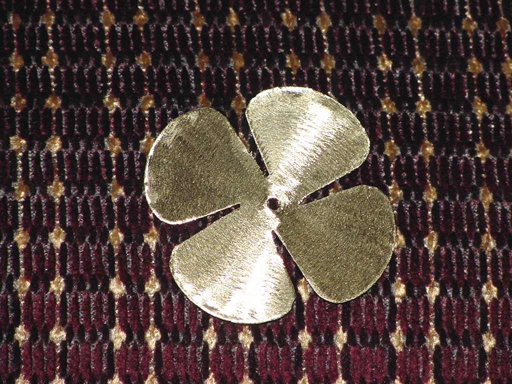
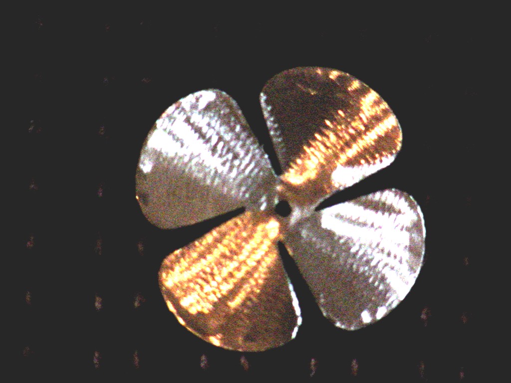
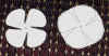
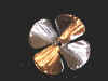 After I got the patterns cut out, I took
the moto-tool and "polished" the brass. Click on the images and notice how it
looks like real turned props on the prototypes. I did this by holding the cutoff disk at
an angle and going from the center outward turning the prop a little with every horizontal
stroke.
After I got the patterns cut out, I took
the moto-tool and "polished" the brass. Click on the images and notice how it
looks like real turned props on the prototypes. I did this by holding the cutoff disk at
an angle and going from the center outward turning the prop a little with every horizontal
stroke.
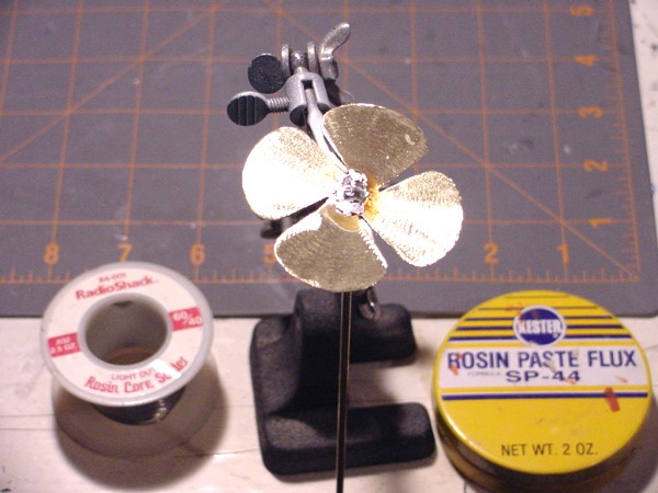
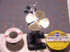 Since I build displacement hulls instead of
fast planning hulls, balance and pitch is not all that important. I use 1/8" brass
rod for my shaft and use a punch to center the hole in the prop and drill it out. I then
place the rod in helping hands and get the alligator clamp level to where the prop will
sit level on it. Then I put paste on the area to be soldered, used a soldering gun to get
it hot and use rosin core solder to solder the prop to the shaft. If you wipe the flux off
while it's still warm it comes off easier.
Since I build displacement hulls instead of
fast planning hulls, balance and pitch is not all that important. I use 1/8" brass
rod for my shaft and use a punch to center the hole in the prop and drill it out. I then
place the rod in helping hands and get the alligator clamp level to where the prop will
sit level on it. Then I put paste on the area to be soldered, used a soldering gun to get
it hot and use rosin core solder to solder the prop to the shaft. If you wipe the flux off
while it's still warm it comes off easier.
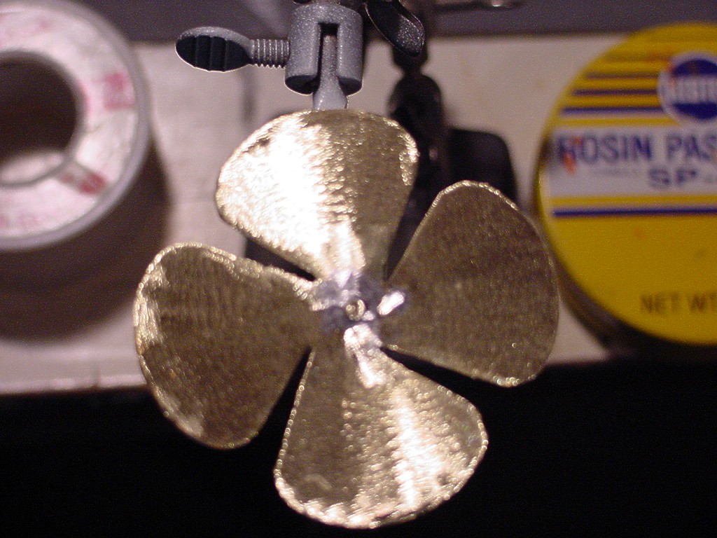
 After the solder cools, I use the moto-tool to
"polish" the solder area and this is how it looks.
After the solder cools, I use the moto-tool to
"polish" the solder area and this is how it looks.
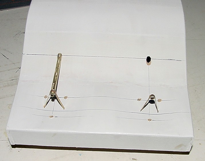
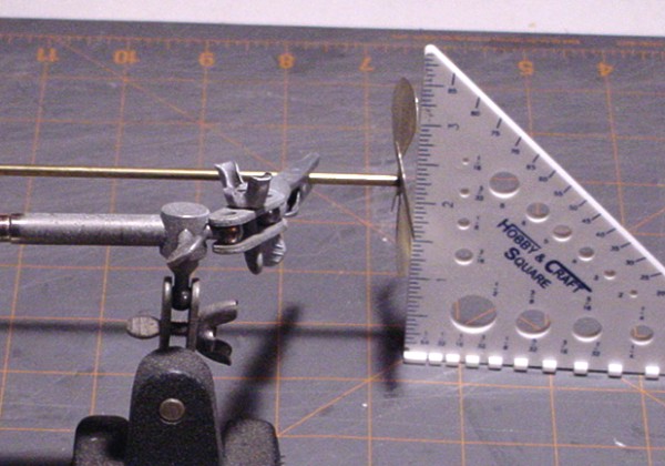
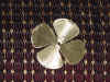
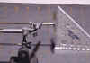 When I finish that, I bend a pitch in the
prop. The more pitch you have the more thrust you have and more load on the motor. If you
use a motor less than 4000rpm or have it geared down, then a sharp pitch is alright. I you
run direct with motors above 5000rpm, then you shouldn't bend as much pitch to it. As you
see in the photo I use a square to get my angle of each blade the same. Use a piece of
3/32" tubing in the clamps so the shaft can be turned. Angle the helping hands
slightly so the top blade won't hit the square. Check the blades at the bottom and bend
until all four brush the square the same. I never balance my props because of the low rpm,
but if you want to try it, below is a home made setup River Bill uses.
When I finish that, I bend a pitch in the
prop. The more pitch you have the more thrust you have and more load on the motor. If you
use a motor less than 4000rpm or have it geared down, then a sharp pitch is alright. I you
run direct with motors above 5000rpm, then you shouldn't bend as much pitch to it. As you
see in the photo I use a square to get my angle of each blade the same. Use a piece of
3/32" tubing in the clamps so the shaft can be turned. Angle the helping hands
slightly so the top blade won't hit the square. Check the blades at the bottom and bend
until all four brush the square the same. I never balance my props because of the low rpm,
but if you want to try it, below is a home made setup River Bill uses.
BALANCING - The PROP
& SHAFT
 Use about a 4" length of scrap - block
wood, and glue a pair of Single or Double - Edge Razor Blades to each end of the block, as
shown in this drawing. Then lay your Drive Shafts & Props, across the balancer to
check them ( as shown in the bottom drawing ). The heavy shaft - side, will roll to the
bottom. That Indicates a need for weight to be removed, so "Polish Off a small
portion of "Solder" around the Prop - in the heavy area, where the fluke is
soldered to the bushing & shaft - itself, to gain a better balance. Then rotate and
recheck - balance again, to insure its right and repeat until correctly balanced. NOTE ... Be sure the table your using to balance
things, is also "LEVEL", before you use this system, it can effect Shaft
balancing. And this balance system, is not made to
adjust "High Speed" props for Race Boats, but works on the same principle - as
theirs do!
Use about a 4" length of scrap - block
wood, and glue a pair of Single or Double - Edge Razor Blades to each end of the block, as
shown in this drawing. Then lay your Drive Shafts & Props, across the balancer to
check them ( as shown in the bottom drawing ). The heavy shaft - side, will roll to the
bottom. That Indicates a need for weight to be removed, so "Polish Off a small
portion of "Solder" around the Prop - in the heavy area, where the fluke is
soldered to the bushing & shaft - itself, to gain a better balance. Then rotate and
recheck - balance again, to insure its right and repeat until correctly balanced. NOTE ... Be sure the table your using to balance
things, is also "LEVEL", before you use this system, it can effect Shaft
balancing. And this balance system, is not made to
adjust "High Speed" props for Race Boats, but works on the same principle - as
theirs do!

 This
is simple, using what's called the "Three Tube" - Brass Tubing Method. One Brass
Tube fits into the other, like a telescoping Antenna. The size of the tubing
required, depends on what your model needs. I use 1/8" rod for shaft, 3/32"
tubing for sleeve bearing, and 5/32" tubing for stuffing box and grease tube. For
large models with props bigger than 2" you should increase the size of the brass. If
you already have props then you will want to start with a shaft that fits the hole in the
prop.
This
is simple, using what's called the "Three Tube" - Brass Tubing Method. One Brass
Tube fits into the other, like a telescoping Antenna. The size of the tubing
required, depends on what your model needs. I use 1/8" rod for shaft, 3/32"
tubing for sleeve bearing, and 5/32" tubing for stuffing box and grease tube. For
large models with props bigger than 2" you should increase the size of the brass. If
you already have props then you will want to start with a shaft that fits the hole in the
prop.